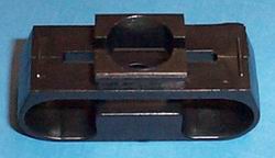
DA-4600 Line
Snap-In Receptacle

Snap-In Receptacle Picture

To Determine Receptacle Size and Stud Length Required

Step 1: Find the Support Thickness Range that applies to your Support Thickness in the table. The Part Number of the receptacle needed is stated to the right of your applicable Support Thickness Range.

Support Thickness
The thickness of the material where the receptacle will be mounted. See Figure below.
Receptacle Selection
Support Thickness Ranges Receptacle Part Numbers X
inch mm inch mm
0.032-0.050 0.81-1.27 4604-2-BK 0.110 2.79
0.064-0.080 1.63-2.03 4604-3-BK 0.143 3.63
0.090-0.104 2.29-2.64 4604-4-BK 0.167 4.24
0.119-0.135 3.02-3.43 4604-5-BK 0.198 5.03
0.149-0.165 3.78-4.19 4604-6-BK 0.228 5.79
Step 2: Calculate the Panel Gap Thickness. Then, in the table below, find the column that applies to the receptacle you selected above and find the Panel Gap Thickness range that applies to your calculated Panel Gap Thickness. The stud length needed is to the far right of your applicable Panel Gap Thickness range.
Panel Thickness
The thickness of the material that contains the stud.
Gap Thickness
The combined thickness of the receptacle top flange (0.055" (1.40 mm)) and stud retainer thickness. These parts may be nested into recessed holes.
Panel Gap Thickness =
Panel Thickness +
Gap Thickness

Snap-In Receptacle Panel Gap Thickness Drawing

English
inch

Receptacles and Panel Gap Thickness Ranges Stud Grip Length
Dimension "G"
4604-2-BK 4604-3-BK 4604-4-BK 4604-5-BK 4604-6-BK
.035-.084 - - - - 45
.085-.134 .035-084 .035-.084 - - 50
.135-.184 .085-.134 .085-.134 .035-.084 .035-.084 55
.185-.234 .135-.184 .135-.184 .085-.134 .085-.134 60
.235-.284 .185-.234 .185-.234 .135-.184 .135-.184 65
.285-.334 .235-.284 .235-.284 .185-.234 .185-.234 70
.335-.384 .285-.334 .285-.334 .235-.284 .235-.284 75
.385-.434 .335-.384 .335-.384 .285-.334 .285-.334 80
.435-.484 .385-.434 .385-.434 .335-.384 .335-.384 85
.485-.534 .435-.484 .435-.484 .385-.434 .385-.434 90
.535-.584 .485-.534 .485-.534 .435-.484 .435-.484 95
.585-.634 .535-.584 .535-.584 .485-.534 .485-.534 100

Metric
mm

Receptacles and Panel Gap Thickness Ranges Stud Grip Length
Dimension "G"
4604-2-BK 4604-3-BK 4604-4-BK 4604-5-BK 4604-6-BK
0.89-2.13 - - - - 45
2.16-3.40 0.89-2.13 0.89-2.13 - - 50
3.43-4.70 2.16-3.40 2.16-3.40 0.89-2.13 0.89.2.13 55
4.70-5.94 3.43-4.67 3.43-4.67 2.16-3.40 2.16-3.40 60
5.97-7.21 4.70-5.94 4.70-5.94 3.43-4.67 3.43-4.67 65
7.24-8.48 5.97-7.21 5.97-7.21 4.70-5.94 4.70-5.94 70
8.51-9.75 7.24-8.48 7.24-8.48 5.97-7.21 5.97-7.21 75
9.78-11.02 8.51-9.75 8.51-9.75 7.24-8.48 7.24-8.48 80
11.05-12.29 9.78-11.02 9.78-11.02 8.51-9.75 8.51-9.75 85
12.32-13.56 11.05-12.29 11.05-12.29 9.78-11.02 9.78-11.02 90
13.59-14.83 12.32-13.56 12.32-13.56 11.05-12.29 11.05-12.29 95
14.86-13.10 13.59-14.83 13.59-14.83 12.32-13.56 12.32-13.56 100

Installation
Support Panel Preparation
Snap-In Receptacle Support Preparation Drawing
Installation Procedures
Snap-In Receptacle Installation Drawing
  1. Angle the long notched side of the top flange into the hole from the underside.
  2. Push the other long side completely through the hole with a flat blade screwdriver.