PA-3500 Line Fastener Installation
- Pre-Assembled 3506-SC and 3522-S Using Hand Squeeze Tool
- Pre-Assembled 3506-SC and 3522-S Using Power-Driven Tools
- Fastener Removal (for 3506-SC and 3522-S stud)
Pre-Assembled 3506-SC and 3522-S
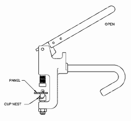
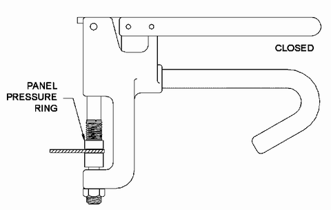
Using Hand Squeeze Tool
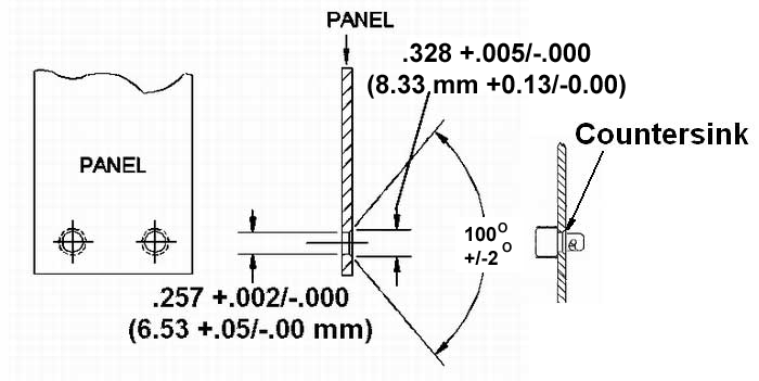
| 1. Drill and countersink hole for stud panel preparation. | |
|
|
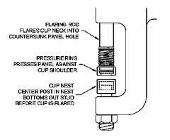
| 2. Insert fastener in cup nest and place panel over stud. | |
|
|
| 3. Ensure panel is firmly against cup shoulder and then squeeze handles to flare cup. | |
|
|
| Fastener | Tool Part Number |
| 3506-SCxxxA-Z3CT | 9916-35-AHT-BB |
| 3522-Sxxx-Z3CT | 9916-35-VSHT-BB |
Troubleshooting:Problem: Probable Cause:
Problem: Probable Cause: Problem: Probable Cause:
|
|
|
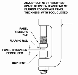
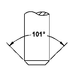
Figure 1: Flaring Rod
|
Figure 2:
|
Pre-Assembled 3506-SC
and 3522-S
Using Power-Driven Tools
| 1. Drill and countersink hole for stud panel preparation. |
|
|
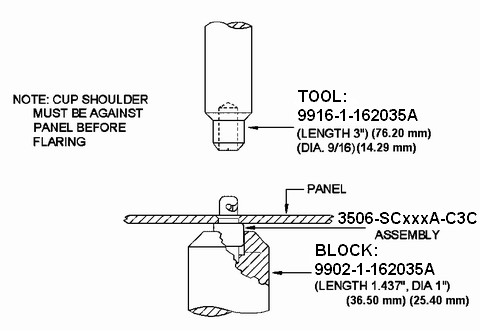
| 2. Insert fastener in block, place panel over stud, ensure cup shoulder is firmly against panel and flare with tool. |
|
| 3506-SC Stud Assembly Tooling |
|
The 9902-1-162035A-BB is used to "bottom out"
the stud in the 3506-SC and press the cup shoulder against the
panel while the 9916-1-162035A-BB flares the cup neck
against the panel.
Both tools are available as a tool set part number 9920-1620-35-1-BB. |
| 3522-S Stud Assembly Tooling |
| Power driven tools are not available for installation of this assembly. |
Troubleshooting:Problem: Probable Cause: Problem: Probable Cause:
Problem: Probable Cause: Problem: Probable Cause: |
Figure 1: Flaring End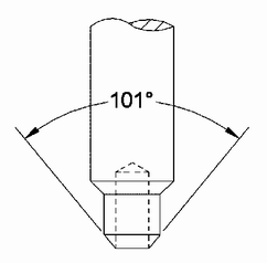
|
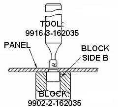
Fastener Removal
(for 3506-SC and
3522-S stud)
|
| 3506-SC or 3522-S Stud Assembly Removal Tooling |
| The 9916-3-162035-BB is used to push the stud and cup out of the panel while a 9902-2-162035-BB block is used to support the panel. |