Stud Panel Preparation
for Oval/Slotted, Phillips Recess,
Hex Recess, and Wing Head Studs
- Stud Panel Preparation for 1219-R, 127P, 127H, and 1219-24
- 1219-R, 127P, and 1219-24 Retainer Installation
- 127H Retainer Installation
- Stud Panel Preparation with 1271 Full Grommet
- 1271 Full Grommet Retainer Installation
- 127S-F Thick Panel Grommet Retainer Installation
Note: Support Preparation is covered under Receptacle Installation
Stud Panel Preparation for 1219-R, 127P, 127H, and 1219-24
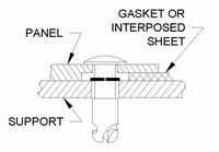
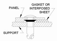
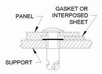
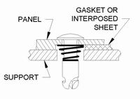
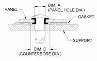
The drawings below all show the stud retainer being absorbed by either a counterbore in the panel, or by the space created through use of a gasket or interposed sheet between the panel and support. If neither option is feasible, the retainer thickness can also be absorbed by either the support or the receptacle when utilizing a 1219-L, 1218-P, 1219-QC4 or 1219-PS receptacle.
|
1219-R
Snap Ring
|
127P
Push-on Grommet
|
127H
Flattened Half Grommet
|
1219-24
Retaining Spring
|
| Stud Size |
Standard Panel Hole Diameter for 127P, 127H, 1219-R, and 1219-24 |
Oversize Panel Hole* Diameter for 127P and 127H |
| + .010 -.000 |
+ .010 -.000 |
|
| 3 | 3/16" | 7/32" |
| 4 | 1/4" | 5/16" |
| 5 | 5/16" | 3/8" |
| 65 | 13/32 | 15/32" |
When using a Gasket or Interposed Sheet, the hole in the gasket or interposed sheet should be sufficiently larger than the outer diameter of the stud retainer to allow free entry of the retainer.
* An oversized panel hole allows the stud to float which can compensate for panel-to-support misalignment. Do not use an oversized panel hole with the 1219-R snap ring retainers.
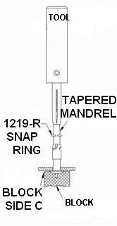
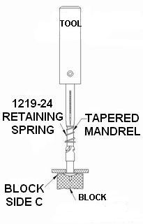
1219-R, 127P, and 1219-24 Retainer Installation
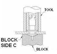
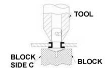
The 9906-RS HAND TOOL is used to push the retainer over a Tapered Mandrel (included) and over the cam end of the stud until it reaches the undercut. Once the retainer reaches the undercut, it snaps back to its original size and prevents the stud from coming out of the panel.
The 9902-1-1 BLOCK Side C is used to support the stud and panel while the retainer is attached.
|
|
127P
Push-on Grommet
|
1219-R
Snap Ring
|
1219-24
Retaining Ring
|
127H Half Grommet Retainer installation
In this case, the 127H Half Grommet Retainer is flattened against the underside of the panel and can cause a gap between the panel containing the stud and the support containing the receptacle. Dimpling the support will allow the panel and support to come into direct contact by allowing the retainer to fit in the dimple. See S-Spring Receptacle Dimpling Tool. |
127H
Flattened Half Grommet
|
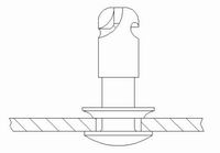
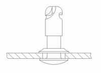
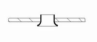
Stud Panel Preparation With 1271 Full Grommet
1271 Retainer wall thickness is absorbed by gasket, interposed panel, or by dimpled support. |
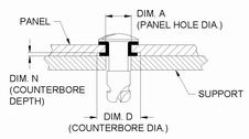
Underside of panel hole is counterbored to depth equal to 1271 Retainer wall thickness. |
*If application requires, size hole +.005/+.010 larger than Dim. A Note: Dimpled panels require dimpled supports. |
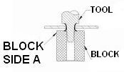
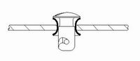
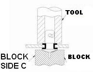
1271 Full Grommet Retainer Installation
| 1. Insert Grommet in Panel Hole |
|
||||||||||||||||
| 2. Set Grommet |
|
|
|||||||||||||||
| 3. Insert Stud |
|
||||||||||||||||
| 4. Clinch Grommet |
|
|
To order installation tools as a set use Part Number:
| Stud Size | Tool Set* Part Number |
| 3 | 9920-1-3-BB |
| 4 | 9920-1-4-BB |
| 5 | 9920-1-5-BB |
| 65 | 9920-1-65-BB |
* Removal tools are not part of the set and must be ordered separately.
| Stud Removal | |||||||||||||||||
|
An installed 1271 or 1276 grommet may be removed by shearing off its underside flange with a staking tool. |
|
|
|||||||||||||||
127S-F Thick Panel Grommet Retainer installation
| 1. Using diameter specified in the table, make the hole in the panel for light press fit grommet. If loose fit is needed, size the hole diameter +.005/+.010" |
|
|||||||||||||
| 2. Press grommet/stud assembly into hole | Note: This stud panel hole permits use of S-Spring receptacles without a dimpled stud hole in support. | |||||||||||||
| 3. Flare grommet. |
|
|
||||||||||||
| 4. Flatten grommet. |
|
|
||||||||||||