Quarter Turn - ST-1200 Line
 Manufactured in the United States of America! |
On-Line Product Selector
|
|
The selection and installation planning of fasteners can influence the security of the fastened parts. Product information and support service is intended for use only by persons with mechanical engineering qualifications sufficient to manage the responsibilities of:
- Analyzing fastener performance in relation to the service to be met, and
- Planning appropriate fastening locations and installations.
The following is a partial list of design criteria which should be used in selecting the correct fastener for your application.
- Tensile Load (average)
- Shear Load (average)
- Maximum Load
- Vibration
- Number of Cycles
- Environmental Concerns
- Appearance
- Mounting Location and Clearance
- Weight
The above considerations, along with the performance chart parameters should be utilized in choosing the appropriate fastener type, head style, receptacle, finish, and materials.
Selection Procedure
| 1. Select a fastener size, using the performance table shown below. The size selected applies to the stud, retainer, and receptacle. | |
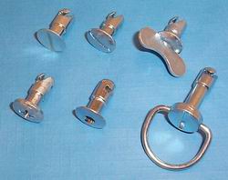
| 2. Select an appropriate stud head style. |
|
3. Select a stud retainer. Some criteria for
retainer selection are:
|
|
|
4. Select a receptacle type.
All of the ST-1200 Line receptacles, except the Press-In type, provide the same optimum performance standards as listed in the Performance Table. |
|
![[ST-1200 Line Stud]](pictures/page38a.gif)
![[ST-1200 Line Receptacle]](pictures/page38b.gif)
5. Now determine the thickness of:
- the material in which the stud is retained (panel),
- any air gaps and any part of the stud retainer thickness not buried in either the panel or support (gap), and
- the material to which the receptacle is attached (support).
|
Then determine the total pileup between the level of stud head contact with the panel (top of Panel) and the level of receptacle contact with the underside of the support (bottom of Support), in the closed position. Refer to the examples on each receptacle page, which will guide you to the Grip Length selection table.
6. Self-ejecting stud assemblies prevent stud play in the open position and provide a visual cue of an open fastener.
|
Stud Part Numbers
|
| Fastener size: | 3 | 4 | 5 | 65 |
| Stud End Diameter: | 3/16 (4.78 mm) |
1/4 (6.35 mm) |
5/16 (7.95 mm) |
13/32 (10.31 mm) |
| Stud Head Diameter: | 5/16 (7.95 mm) |
7/16 (18.75 mm) |
9/16 (14.30 mm) |
11/16 (17.48 mm) |
| Locked Service Tension (lb): | 20 | 30 | 45 | 55 |
| Max. Tension w/o Distortion (lb): | 45 | 60 | 85 | 110 |
| Rated Shear (lb): | 100 | 150 | 200 | 300 |
| Wear Life (Thousands of uses): | 5 | 5 | 25 | 40 |
Maximum Sheet Separation at 150% of Locked Service Tension: .05" (1.27 mm)