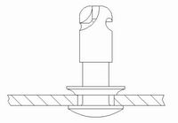
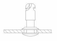
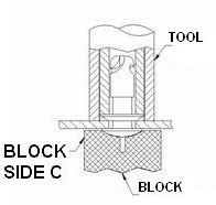
Stud Panel Preparation
for Flush Head Studs
Flush Head Studs
Panel Preparation for 1276 Grommet
Installation of a 1276 Full Grommet Retainer is a multi-step
process and requires several different tools.
|
Flush Head Stud using type 1276 Full Grommet Retainer
|
| 1. Drill Hole |
| Stud Size |
Hole Diameter |
| 4 |
17/64" |
| 5 |
5/16" |
| 6 |
3/8" |
| 65 |
7/16" |
| 7 |
15/32" |
|
2. Dimple Hole |
| Stud Size |
Tool Part Number |
Block Part Number |
| 4 |
9916-1-64-BB |
9902-1-64-BB |
| 5 |
9916-1-65-BB |
9902-1-65-BB |
| 6 |
9916-1-66-BB |
9902-1-66-BB |
| 65 |
9916-1-665-BB |
9902-1-665-BB |
| 7 |
9916-1-67-BB |
9902-1-67-BB |
|

|
| 3. Install Grommet |

|
| 4. Set Grommet |
| Stud Size |
Tool Part Number |
Block Part Number |
| 4 |
9916-3-64-BB |
9902-3-64-BB |
| 5 |
9916-3-65-BB |
9902-3-65-BB |
| 6 |
9916-3-66-BB |
9902-3-66-BB |
| 65 |
9916-3-665-BB |
9902-3-665-BB |
| 7 |
9916-3-67-BB |
9902-3-67-BB |
|

|
| 5. Insert Stud and Clinch Stud |
| Stud Size |
Block Part Number |
| 4 |
9902-3-64-BB |
| 5 |
9902-3-65-BB |
| 6 |
9902-3-66-BB |
| 65 |
9902-3-665-BB |
| 7 |
9902-3-67-BB |
|

|
|
Note:
Dimpled Panels require Dimpled Supports.
|
Panel Preparation for Reverse Clinched Hole
(No Stud Retainer)
Installation in a dimpled and reverse-clinched panel stud
hole is a multi step process.
| 1. Drill Hole |
Stud
Size |
Hole
Dia. |
MAX Panel Thickness
for Dimpling |
| 3 |
9/64" |
.030" |
| 4 |
13/64" |
.040" |
| 5 |
15/64" |
.050" |
| 65 |
21/64" |
.078" |
|
| 2. Dimple Hole |
Stud
Size |
Tool Part Number |
Block Part Number |
| 3 |
9916-1-6-N3-BB |
9902-1-6-N3-BB |
| 4 |
9916-1-6-N4-BB |
9902-1-6-N4-BB |
| 5 |
9916-1-6-N5-BB |
9902-1-6-N5-BB |
| 65 |
9916-1-6-N65-BB |
9902-1-6-N65-BB |
|

|
| 3. Insert Stud |

|
| 4. Clinch Stud |
Stud
Size |
Block Part Number |
| 3 |
9902-3-6-N3-BB |
| 4 |
9902-3-6-N4-BB |
| 5 |
9902-3-6-N5-BB |
| 65 |
9902-3-6-N65-BB |
|

|
|
Note:
Dimpled Panels require Dimpled Supports.
|
Panel Preparation for 1219-R, 127H, and 127P
| 1. Drill and countersink holes |
| Stud Size |
Dim. A
+.010"
-.000" |
Dim. B
+.010"
-.000" |
Dim. C
+.010"
-.000" |
| 3 |
.367" |
.188" |
.051" |
| 4 |
.508" |
.250" |
.074" |
| 5 |
.633" |
.313" |
.092" |
| 65 |
.757" |
.407" |
.095" |
|

|
2. Install stud retainer
1219-R and 127P Retainer Installation
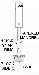
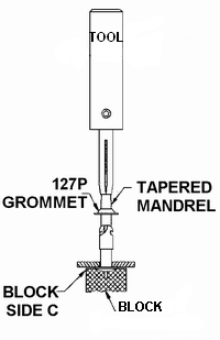
9906-RS HAND TOOL is used to push the retainer over a
Tapered Mandrel (included) and over the cam end of the stud
until it reaches the undercut. Once the retainer reaches the
undercut, it snaps back to its original size and prevents
the stud from coming out of the panel.
Any flat block may be used to support the Flush Head
Stud while the retainer is attached.
|
1. Place the stud head on the support
and place the stud through the panel.
Use a Flat Surface Plate in place of the block.
|
|
| 2. Place the retainer on mandrel. |
|
| 3.Align ring or spring ends so that they will miss the stud cam. |
|
| 4. Place the mandrel in end of stud cam and place the tool over mandrel |
Stud
Size |
Tool Part Number |
| 3 |
9906-RS-3-BB |
| 4 |
9906-RS-4-BB |
| 5 |
9906-RS-5-BB |
| 65 |
9906-RS-65-BB |
|
| 5. Push retainer until it is seated in the stud undercut. |
|
|
1219-R
Snap Ring
|
127P
Push-on Grommet
|
127H Half Grommet Retainer installation
|
|
Note:
This stud panel hole permits use of S-Spring receptacles
without a dimpled stud hole in support.
|
Panel Preparation for 127S-F
Thick Panel Grommet Retainer
Installation of a 127S-F Thick Panel Grommet Retainer is also
a multi-step process and requires several different tools.
|
1. Make hole in panel for grommet press fit, then countersink
and counter bore.
|
| Stud Size |
Dim. A |
Dim. B |
Dim. C |
| 3 |
.328" |
.219" |
.030" |
| 4 |
.453" |
.313" |
.043" |
| 5 |
.578" |
.375" |
.045" |
|

|
|
2. Press grommet/stud assembly into hole
|
|
3. Flare grommet using flaring tool.
|
| Stud Size |
Flaring Tool
Part Number |
| 3 |
9906-A-3-BB |
| 4 |
9906-A-4-BB |
| 5 |
9906-A-5-BB |
|

|
|
4. Flatten grommet using tool.
|
| Stud Size |
Tool Part Number |
| 3 |
9916-3-13-BB |
| 4 |
9916-3-14-BB |
| 5 |
9916-3-15-BB |
|

|
|
Note:
This stud panel hole permits use of S-Spring receptacles
without a dimpled stud hole in support.
|
|


