UN-5700 Line Installation
Receptacle
Rigid
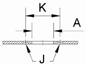
1. Drill holes and countersink rivet holes of support panel.
inch
| Stud Size |
A
±.010 |
K
±.005 |
J |
| 3 |
.344 |
.625 |
.096 |
| 4 |
.468 |
.750 |
.096 |
| 5 |
.703 |
1.000 |
.128 |
|
mm
| Stud Size |
A
±0.25 |
K
±0.13 |
J |
| 3 |
8.74 |
15.88 |
2.44 |
| 4 |
11.89 |
19.05 |
2.44 |
| 5 |
17.86 |
25.40 |
3.25 |
|
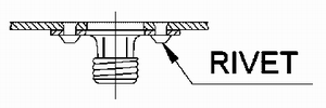
2. Rivet receptacle
Floating
1. Drill holes and countersink rivet holes of support panel
inch
| Stud Size |
A
±.010 |
K
±.005 |
J |
| 3 |
.344 |
.625 |
.096 |
| 4 |
.468 |
.750 |
.096 |
| 5 |
.703 |
1.000 |
.128 |
|
mm
| Stud Size |
A
±0.25 |
K
±0.13 |
J |
| 3 |
8.74 |
15.88 |
2.44 |
| 4 |
11.89 |
19.05 |
2.44 |
| 5 |
17.86 |
25.40 |
3.25 |
|
2. Insert spacers and rivet receptacle
Press Fit
Type 127H grommets may be used to retain studs when support
thickness exceeds .070" for 5718-FP3-ACNC and .094" for
5718-FP4-ACNC receptacles. For thinner supports, 5725-166-C3Y
retaining ring must be used for size 3 studs and 5723-A514-C3Y
retaining ring for size 4 studs. Retaining ring should be slipped
around stud shaft and closed with pliers in undercut section of
stud.
1. Drill hole

|
| Receptacle Size |
Hole Diameter |
| inch |
mm |
| 3 |
.406 +.003 / -.001 |
10.31 +.08 / -.03 |
| 4 |
.500 +.003 / -.000 |
12.70 +.08 / -.03 |
|
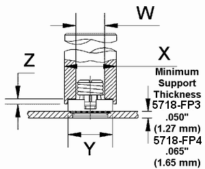
2. Make a press in tool using dimensions below
| Part Number |
Tool Dimensions |
| W |
X |
Y
+.005 / -.000
(+.13 / -.00 mm)
|
Z |
| inch |
mm |
inch |
mm |
inch |
mm |
inch |
mm |
| 5718-FP3-ACNC |
.344 x .625 deep |
9.58 x 15.88 deep |
.624 |
15.88 |
.505 |
12.55 |
.125 |
3.18 |
| 5718-FP4-ACNC |
.453 x .625 deep |
11.51 x 15.88 deep |
.750 |
19.05 |
.630 |
16.00 |
.156 |
3.96 |
|
3. Press in.
|


